Diffraction of X-rays by Crystals
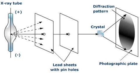
X-rays are electromagnetic radiation of high penetrating power and short wavelength, which are emitted from a target when it is bombarded with high-energy electrons as illustrated in Figure 1. These high-energy electrons knock out the tightly bound electrons in the K or L electronic shells of the target material. The low-energy empty levels thus created are filled by falling back of the electrons from higher energy levels to the inner levels. The energy liberated during this process is in the form of X-rays.
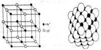
Max von Laue (1912) suggested that the wavelengths of X-rays are of the same order of magnitude as the spacing between ions or atoms in a crystal such as that of NaCl. The crystals would, therefore, act as a three-dimensional diffraction grating for X-rays in much the same way as a grating diffracts visible lights. These predictions were soon found to be essentially correct.
The diffraction effect occurs when radiation is disturbed from its direction of propagation so that some of the waves of the radiation are shifted out of phase with other waves due to scattering. As a result, interference will occur. When the waves are in phase at a point the intensity there will increase due to constructive interference, while if the waves meet when they are out of phase destructive interference decreases the intensity of the radiation at these points. The final effect is a diffraction pattern.
W.H. Bragg and his son Lawrence considered the phenomenon of diffraction of X-rays by crystals and pointed out that it is convenient to think of the X rays as being ‘reflected’ from successive planes of ions or atoms in the crystal when a beam of X-rays falls on such a crystal. Consider in figure-1 a set of parallel planes in the crystal structure and a beam of X-rays of wavelength λ, incident on the planes at an angle θ.
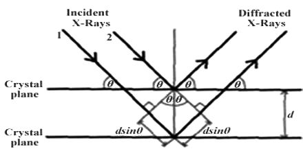
Fig:1 Reflection of X-rays from crystal planes
The planes are separated by a distances d. The X-rays will be reflected from different planes. The beam reflected from the first plane, example when the difference in the path of the two beams is in an integral multiple of the wavelength. This happens when the relation holds.
nλ = 2d sinθ; where n = 1, 2, 3, ….
This is the famous Bragg equation. The experimental arrangement which Bragg set up for making use of equation (4.1) is shown in Figure-2.
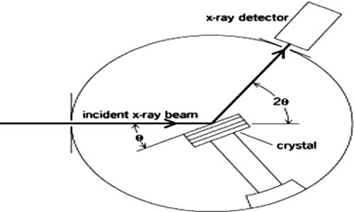
Fig-2: X-rays diffraction apparatus.
An X-ray beam generated in the X-ray tube is made monochromatic and parallel as far as possible by optical means and then allowed to fall on to a known face of the crystal, mounted on a rotating table. The position of the table is read off the scale over which the arm of the rotating table moves. The radiation reflected from the crystal is led into a detecting device which is usually an ionization chamber. The current produced by the ionization of an easily ionizable gas, such as methyl bromide, in this chamber, is measured by means of an electrometer. The current is a measure of the intensity of radiation. The ionization chamber may also be rotated around the same axis as the crystal. This chamber is rotated at twice the rate of the rotation of the table carrying the crystal. The intensity of ionization produced at different angles are measured by the electrometer and these are plotted against 2θ.
There were maxima in the graphs and these must coincide with the angles for which the Bragg equation, nλ = 2d sinθ, holds. The maxima corresponding to n = 2, 3—, are known as first-order, second-order, third-order etc reflections. The curves obtained for sodium chloride and potassium chloride crystals are shown in Figure-3.
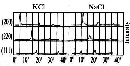
Fig-3: graph of intensity against 2θ for NaCl and KCl
In order to determine d, the spacing of the planes of Atom or ions in the crystal from X-ray measurements the wavelength of the incident X-ray beam must be known. Nowadays X-ray tubes are available which give a monochromatic X-ray beam of known wavelength. X-ray tubes with a copper target which gives off a beam with the wavelength equal to 15.40 nm are in common use.
