Experimental Determination of Conductance
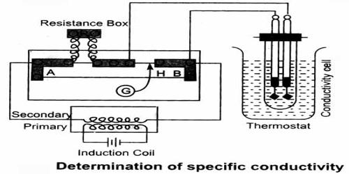
The basic principle of the experimental determination of electrolytic conductance is that of the Wheatstone’s bridge. A simplified circuit diagram of a conductance bridge is shown in Figure. This conductance bridge was originally devised by Kohlrausch, and is known as Kohlrausch’s conductance bridge. For measuring conductance of solutions direct current cannot be used because electrolysis will take place and polarization of the electrodes occurs; further complication will be caused by evolution of gases in many cases. Also secondary reactions at the electrodes will spoil the experiments. This difficulty has been eliminated by use of high frequency alternating current from a small induction coil called a ‘buzzer’ or better from an oscillator. The a-c source generates usually 1-3 kilo cycles/sec. Due to rapid change of polarity at the electrodes polarization is reduced considerably and electrolysis is stopped. The galvanometer in the Wheatstone’s bridge circuit is generally replaced by a small sensitive telephone.
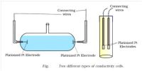
a-c current is generated from the ‘buzzer’ by a storage battery. Two wires connect the a-c source to the two ends of the meter bridge at M-M. In the gap R is placed a variable decade resistance. M, M and M’ are thick metal plates. The solution is placed in a special conductance cell, C, which is connected to the other gap in the bridge between M and M’. The detector, in this case the telephone, is connected to M’ and a sliding jockey, S, that connects to the bridge wire AB. A scale, usually one metre long and graduated in millimeters, runs along the wire. The jockey, S, can be moved along the wire so that each position of the jockey represent a definite resistance in the wire.
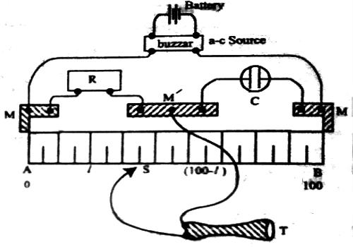
Figure: Schematic diagram of Wheatstone bridge
When the circuit is completed a buzzing sound is heard in the telephone. A suitable resistance (R) is placed in the gap, R. The sliding contact is then moved along the wire until there is no sound in the phone or the sound is minimum. This is the null point. The resistance is usually so chosen that the null point is at about the middle of the scale. If the length of the wire, AB, is 100 cm and null point is at a distance ‘l’ cm from the end A, then the principle of the Wheatstone’s bridge gives.
R / Cell resistance = l / (100 – l)
or, Cell resistance = R [(100 – l) / l]
or, Cell reluctance = l / R(100 – l)
Since ‘l’ and ‘R’ are known the conductance of the solution in the cell is at once calculated.
This simple bridge can give only moderately good values of conductance. It is very difficult and sometimes impossible to get a sharp minimum in the bridge. Use of a small variable parallel plate condenser, like one used in a radio for tuning, connected parallel to the conductivity cell imprints the minimum, but even then there are other sources of error.
Many good and sophisticated bridges are commercially available. The principle of all these bridges is the same as above but the a-c current is generated by an electronic oscillator. For better sensitivity the current is amplified before being fed to the detector.
The detector generally is a cathode-ray tube (magic eye as in a radio) or in more expensive and sensitive instruments it is a cathode ray oscilloscope. Precise and reliable conductance values can be obtained from such improved instruments only.