A transistor is a device that regulates current or voltage flow and acts as a switch or gate for electronic signals. It can act as a switch and an amplifier. It converts audio waves into electronic waves and resistor, controlling electronic current.
Common Emitter Amplifier:
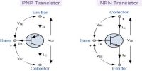
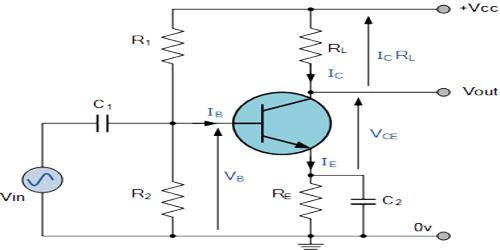
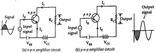
The common emitter amplifier is a three basic single stage bipolar junction transistor and is used as a voltage amplifier. In the figure, the circuit diagram of a common emitter amplifier has been shown. Figure (a) shows the circuit diagram of a ‘n-p-n’ and figure (b) shows the circuit diagram of a ‘p-n-p’ amplifier. Here input signal is applied between base and emitter and output is taken from the emitter and collector. Since emitter is common to both the base input and output, hence it is called a common emitter amplifier.
In addition to a.c. signal here a battery (VBB) has been used in the input circuit. This d.c. voltage is called bias voltage. Its value is such that during a negative half cycle of the applied a.c. signal the emitter-base junction remains forward biased. Otherwise, the emitter-base junction will be reverse biased and no current will be obtained in the output circuit. Consequently, the amplifier will lose reliability. In figure 2, current flow IC is due to an application of VB in the input circuit.
Working principle
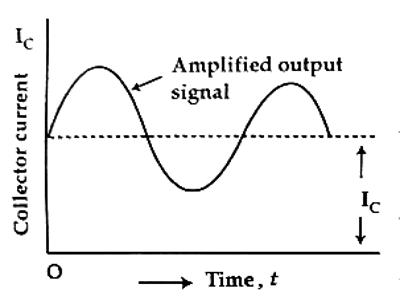
For the positive half-cycle of the input signal applied to the emitter-base junction, the junction becomes (onward biased. So, more electrons flow from the emitter through the base to the collector and the collector current increases. This increased collector current (IC) creates more voltage drop across the load resistance (RC). During the negative half cycle of the input signal as the emitter-base becomes reverse biased, so forward bias in the junction decreases, hence collector current also decreases. As a result, the output voltage of the circuit will be relatively small (in the reverse direction). In this way, the amplified output of a transistor is produced. The phase difference of this amplified output and input is 180°. In figure Fig. 2, the variation of current with time for a complete cycle has been shown.
Uses of transistor amplifier:
- It is used in the intercom.
- It is used in the alarm circuit.
- It is used in radio.
- It is used in microphone.