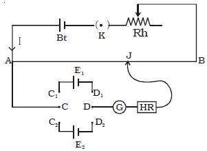
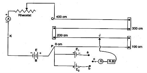
A potentiometer is a mechanism used to evaluate the e.m.f. (electromotive force) of two cells, to calculate the internal resistance of a cell, and potential difference transversely a resistor. The potentiometer wire AB is connected in series with a battery (Bt), Key (K), rheostat (Rh) as shown in Figure. This forms the primary circuit. The end A of the potentiometer is connected to the terminal C of a DPDT switch (six-way key−double pole double throw). It consists of a long wire of uniform cross-sectional area and of 10 m in length. The substance of wire should have a high resistivity and low-temperature coefficient. The wires are prolonged parallel to each other on a wooden board. The wires are fixed in series by using thick copper strips. The terminal D is connected to the jockey (J) through a galvanometer (G) and high resistance (HR). The cell of emf E1 is connected between terminals C1 and D1 and the cell of emf E2 is connected between C2 and D2 of the DPDT switch. A meter scale is also attached on the wooden board.
Apparatus: Potentiometer, a Leclanche cell, a Daniel cell, an ammeter, a voltmeter, a galvanometer, a battery, a rheostat of low resistance, a resistance box, a one-way key, a two-way key, connecting wires and a piece of sandpaper.

Fig: comparison of emf of two cells
The potentiometer works on the theory that when a stable current flows through a wire of uniform cross-sectional area, the potential dissimilarity between its two points is straight proportional to the length of the wire between the two points.
Let I will be the current flowing through the primary circuit and r be the resistance of the potentiometer wire per meter length.
The DPDT switch is pressed towards C1, D1 so that cell E1 is included in the secondary circuit. The jockey is moved on the wire and adjusted for zero deflection in the galvanometer. The balancing length is l1.
The potential difference across the balancing length l1 = Ir l1. Then, by the principle of the potentiometer,
E1 = Ir l1 … (1)
The DPDT switch is pressed towards E2. The balancing length l2 for zero deflection in galvanometer is determined. The potential difference across the balancing length is l2 = Ir l2, then
E2 = Ir l2 … (2)
Dividing (1) and (2) we get
E1/E2 = l1/ l2
If emf of one cell (E1) is known, the emf of the other cell (E2) can be calculated using the relation.
E2 = E1 (l2/ l1)
Electromotive force (e.m.f) of a cell
Electromotive force (emf) is a measurement of the energy that causes current to flow throughout a circuit. Assessment of emf of two cells: First of all the ends of the potentiometer is joined to a battery B1, key K and rheostat Rh such that the positive terminal of battery B1 is connected to end A of the wire. It is the energy provided by a cell or battery per coulomb of charge passing through it. This completes the main circuit.
It can also be defined as the potential difference across the terminals of a cell when no current flows through it. Now the optimistic terminals of the cells C1 and C2 whose emfs are to be compared are connected to A and the negative terminals to the jockey J through a two-way key and a galvanometer. This is the secondary circuit. Electromotive force is also known as voltage, and it is measured in volts. Electromotive force is not really a force; rather, it is a capacity of energy per unit charge.


