Experiment: To determine the specific resistance (resistivity) of a wire by meter bridge
Theory: The amount of resistance or hindrance that a conductor having unit length and the unit area offers to the flow of current is called a specific resistance of that conductor. It is denoted by ρ.
If the length of a wire is L, the area of cross-section is A and total resistance is Q, then its specific resistance is –
ρ = QA/L
If the wire is cylindrical or circular then cross-section, A = πr2.
Here, r = radius of the wire.
Specific resistance, ρ = Qπr2 / L … … … (1)
If R is expressed in the practical unit and L and r are expressed in meter, then the unit of ρ will be ohm-meter (Ω-m).
The total resistance Q in the equation (1) can be determined by a meter bridge according to the following theory.
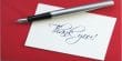
In the left of the two gaps of the meter bridge a known resistance P and in the right gap an unknown resistance Q is inserted [Figure] and after completing the circuit if the distance of the null point is l from the left terminal and if σ is the resistance of the unit length of the wire, then applying Wheatstone principle we get,
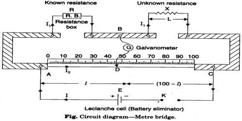
P/Q = R/S = [Resistance of length l of the bridge wire / Resistance length (100 – l) of the bridge wire]
or, P/Q = R/S = lσ / (100 – l)σ = l / (100 – l)
or, Q = [P x (100 – l)] / l ohm … … … (2)
Again, by changing the position of the resistances i.e., known resistance P in the right gap and unknown resistance Q in the left gap, we get,
Q/P = l / (100 – l)
or, Q = P x l / (100 – l) ohm … … … (3)
From the average value of the equations (2) and (3), we can find out the unknown resistance Q.
By measuring the radius r, length L of the wire and by determining the unknown resistance by the meter bridge and then inserting these values in equation (3) we can find out the value of the specific resistance of the wire.
Description of the wire:
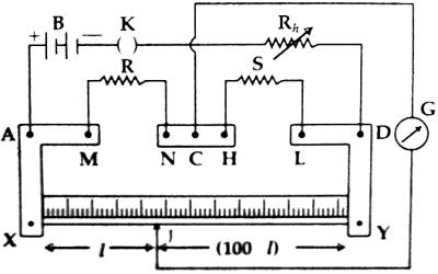
It consists of three thick copper or brass strips XAM, NCH and LDY mounted on a long wooden board [Figure-2]. The resistances of these strips are negligible and there is a connecting screw at each point of A, M, N, C, H, L, and D. There is a meter scale placed between the strips XAM and LDY. A straight wire of lm long and of a uniform cross-section is attached at points X and Y along the length of the scale. A 1-meter long wire is used as a resistor; hence it is called a meter bridge.
Necessary instruments: (1) A meter bridge, (2) electric cell, (3) galvanometer, (4) resistance box. (5) commutator or key, (6) jockey, (7) connecting wires, (8) screw gauge, (9) meter scale, (10) experimental wire etc.
Procedure:
- The circuit is drawn in a rough notebook.
- The connection is made according to the circuit diagram.
- The unknown resistance Q is connected to the right gap and the known resistance P is connected to the left gap of the bridge. The galvanometer is connected from the midpoint of the meter bridge and through the resistance box to the jockey J or a push key.
- After completing the circuit connecting the jockey is touched at one end of the wire of the bridge and the deflection of the galvanometer is observed. Again the jockey is touched at the other end of the meter bridge and deflection is noticed. If these two deflections are found opposite then it is considered that the circuit connection is alright.
- A known resistance P1 is applied in the circuit from the resistance box. Now holding the jockey on the wire it is moved right and left and a position on the wire is fixed where at the galvanometer does not show any deflection. This is the null point. The length l1 is determined from the left of the meter scale attached to the bridge. Inserting these values into equation (2) the value of Q is found out.
- Now positions of P and Q are interchanged. Keeping the value of P1 fixed following the above procedure the null point is found out and the length l2 up to that point is noted. These values are inserted in equation (3) and Q1 is found out.
- By interchanging the positions of P and Q are taken to the earlier position. A resistance P2 of different value is withdrawn from the box P and following procedures (5) and (6) unknown resistances Q2 and Q2‘ are found out.
- Following the procedure (7) resistance P3 is taken out from the resistance box P and following the previous procedures Q3 and Q3΄. are found out.
- Now taking the average values of Q1, Q1‘, Q2, Q2‘ and Q3 and Q3‘ the unknown resistance Q ohm is found out.
- By removing the experimental wire from the meter bridge its average length is measured by a meter scale.
- Diameter i.e., the radius of these wire is measured by a screw gauge and cross-sectional area of the wire is determined.
- Inserting the experimental values of Q, L and r in equation (2), the specific resistance of the wire is calculated.
Precaution
While observing the experiment some problems were found due to some reasons.
- The wire used may not be a uniform area of cross-section. So, it is necessary to choose a proper wire.
- All the connections and plugs must be tight.
- The jockey must be moved gently over the meter bridge wire.
- It is necessary to take find out the diameter of the wire exactly.
- The percentage of error increases if the resistance box or other materials may not be clean.
- The reading of the screw gauge might be accurate.