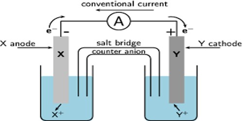
Measurement of E.M.F of Electrochemical Cells
When current is drawn from a cell its e.m.f. gradually drops as chemical energy is being converted into electrical energy. In order to obtain correct e.m.f of the cell, the measurements should be carried out in such a way that no current is drawn from the cell. Since this is not possible in practice, the measurement is carried out under conditions in which the current drawn from the cell is so small as to be negligible. The principle of the method was first described by Poggendorff and the method is known as the Poggendorf’s compensation method.
In this method, the unknown e.m.f. of a cell is opposed by a cell of known e.m.f. and hence the name compensation method. The potential difference between the two electrodes in a galvanic cell is called a cell potential or emf of the cell. It is measured in volts. The electrical circuit he used is known as a potentiometer circuit.
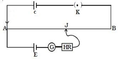
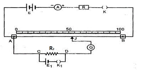
Fig: Principle of a potentiometer
An electrode at which oxidation takes place is an anode and the electrode at which reduction takes place is a cathode. The basic potentiometer circuit is shown in Figure. When a metal is in contact with its own ion solution it develops a potential with respect to the electrolyte. AB is a wire of uniform resistance. The ends A and B of the wire are connected to the two electrodes of a lead storage battery C, through a variable resistance, R. Along the wire AB there is a gradual fall of potential which is proportional to the length of the wire. One electrode of the cell, E, whose e.m.f is to be measured, is connected through a galvanometer, G to A. The other electrode is connected through a key, K, to AB by a sliding contact D. The potential difference between the anode and cathode is called the EMF of the cell.
After pressing the key K the contact D is moved along the wire until there is no deflection of the galvanometer, indicating that no current is flowing. At this position the fall of potential along the wire AB from A to D is equal to the potential of the cell E. If now the cell E is replaced by a standard cell, the potential of which is very accurately known, a new position of the contact, D’, is found when no current flows through the galvanometer. At this position –
(Length of the wire with cell E)/( Length of the wire with standard cell S) =
(Potential of the cell E)/(Potential of the standard cell S)
From the known value of the potential of the standard cell, S, and the experimentally determined value of the lengths of wire, the potential of the cell, E, may be obtained.
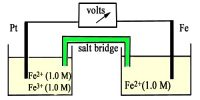
Alternately a high resistance voltmeter could be connected to the two electrodes of the two half – cells and the trial of the cell is read directly. A high resistance voltmeter allows only a small amount of current to pass and does not change the concentrations of the electrolytes significantly.
For actual measurements, an instrument called the potentiometer is used. The basic principle is the same as above but instead of the length of wire, there are two circular resistances, R1 and R2, as shown in Figure- 2, which are directly calibrated in volts.
The instrument is first set by placing a standard cell in the circuit, setting the dials for R1 and R2 to read the potential of the standard cell, and adjusting the variable resistance, R, so that no current passes through the galvanometer, G. The standard cell is now replaced by the experimental cell and keeping the setting of R fixed the dials for R1 and R2 are adjusted until again no current passes through the galvanometer. The e.m.f. of the cell is read off directly from the dials for R1 and R2. This method is capable of giving results of high accuracy.
