An alternating source of emf is connected across a capacitor of capacitance C (Figure: a). It is charged first in one direction and then in the other direction.
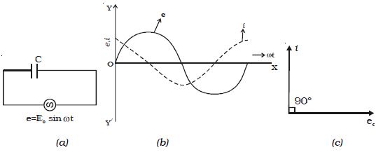
Fig: Capacitive circuit
The instantaneous value of the applied emf is given by
e = E0 sin ωt …(1)
At any instant, the potential difference across the capacitor will be equal to the applied emf
∴ e = q/C, where q is the charge in the capacitor
But i = dq/dt = d/dt (Ce)
i = d/dt (C E0 sin ωt) = ω CE0. cos ωt
i = E0/(1- ωC) sin (ωt + π/2)
i = I0 sin (ωt + π/2) … … (2)
where I0 = E0 (1/ωC)
1/ωC = XC is the resistance offered by the capacitor. It is called capacitive reactance. Its unit is ohm.
From equations (1) and (2), it follows that in an a.c. circuit with a capacitor, the current leads the voltage by a phase angle of π/2. In other words, the emf lags behind the current by a phase angle of π/2.
This is represented graphically in Fig: b. Fig: c represents the phasor diagram of a.c. the circuit containing only C.
∴ XC = 1/ωC = 1/ (2π νC)
where ν is the frequency of the a.c. supply. In a d.c. circuit ν = 0
∴ XC = ∞
Thus a capacitor offers infinite resistance to d.c. For an a.c. the capacitive reactance varies inversely as the frequency of a.c. and also inversely as the capacitance of the capacitor.