The three-phase power is generally used for transmission and allocation of electrical power because of their advantage. This has properties that make it very advantageous in electric power systems. It is more inexpensive as evaluate to single phase power and requires three live conductors for power supply. Here, power is usually generated and distributed in three phase and transformers are used to alter the voltage.
Generation of three-phase emf
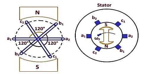
In a three – phase a.c. generator three coils are fastened rigidly together and displaced from each other by 1200. It is made to rotate about a fixed axis in a uniform magnetic field. Each coil is provided with a separate set of slip rings and brushes.
These voltages can be produced by a three-phase AC generator having three identical windings displaced separately from each other by 120 degrees electrical. Three electrical circuits/coils are equally distributed over the margin of a permanent magnetic rotor. Three phase systems may or may not have an impartial wire. An impartial wire allows the three-phase structure to use a higher voltage while still sustaining lower voltage single phase appliances. The scale and incidence of these EMFs are similar but are displaced separately from one another by an angle of 120 degrees.
An emf is induced in each of the coils with a phase difference of 120o. Three coils a1 a2, b1 b2, and c1 c2 are mounted on the same axis but displaced from each other by 1200, and the coils rotate in the anticlockwise direction in a magnetic field (Fig: a).
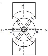
Fig; a Section of 3 phase ac generator
When the coil a1 a2 is in position AB, emf induced in this coil is zero and starts increasing in the positive direction. At the same instant, the coil b1b2 is 120o behind coil a1a2, so that emf induced in this coil is approaching its maximum negative value and the coil c1 c2 is 2400 behind the coil a1 a2, so the emf induced in this coil has passed its positive maximum value and is decreasing.
According to Faraday’s law, emf induced in three coils. The emf induced in these three coils will have phase dissimilarity of 1200. i.e. if the induced emf of the coil C1 has a phase of 00, then induced emf in the coil C2 lags that of C1 by 1200 and C3 lags that of C2 1200.
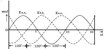
Fig: b Three phase emf
Thus the EMFs induced in all the three coils are equal in magnitude and of the same frequency. The emf induced in the three coils are;
ea1a2 = E0 sin ωt
eb1b2 = E0 sin (ωt – 2π/3)
ec1c2 = E0 sin (ωt – 4π/3)
The emf induced and phase difference in the three coils a1 a1, b1 b1 and c1 c1 are shown in Fig: b & Fig:c.
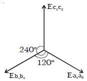
Fig: c Angular displacement between the armature
A three-phase method is equal if and only if:
- A load of each phase has equal impedance value;
- A load impedance of each phase has an equivalent phase angle;
- Voltage and current values are equivalent for each phase and;
- Phase disarticulation is 1200 between each phase.
