Working Process of AC Dynamo
Whenever, there is a change in orientation of the coil, the magnetic flux linked with the coil changes, producing an induced emf in the coil. The direction of the induced current is given by Fleming’s right hand rule.
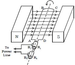
Suppose the armature ABCD is initially in the vertical position. It is rotated in the anticlockwise direction.
The side AB of the coil moves downwards and the side DC moves upwards (Figure). Then according to Flemings right hand rule the current induced in arm AB flows from B to A and in CD it flows from D to C. Thus the current flows along DCBA in the coil. In the external circuit the current flows from B1 to B2.

Fig: AC dynamo
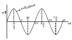
On further rotation, the arm AB of the coil moves upwards and DC moves downwards. Now the current in the coil flows along ABCD. In the external circuit the current flows from B1 to B1. As the rotation of the coil continues, the induced current in the external circuit keeps changing its direction for every half a rotation of the coil. Hence the induced current is alternating in nature (Figure). As the armature completes ν rotations in one second, the alternating current of frequency ν cycles per second is produced. The induced emf at any instant is given by e = E0 sin ωt

Fig: emf varies sinusoidally
The peak value of the emf, E0 = NBAω
where N is the number of turns of the coil,
A is the area enclosed by the coil,
B is the magnetic field and
ω is the angular velocity of the coil


