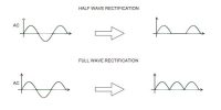
Experiment: Full Wave Rectification (Using two diodes)
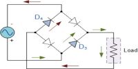
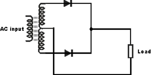
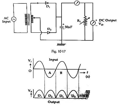
Full wave rectification can be achieved by two diodes. In a Full Wave Rectifier circuit two diodes are now used, one for each half of the cycle. Let V = Vm Sinθ the alternating voltage. Suppose diode resistance is ‘R’ and load resistance is RL. In case of forward biasing current flows through the diodes. But during reverse bias current flowing through it is very small (I μA). Rectifier is used for converting AC flow info DC flow. During the positive half cycle current flows and during negative half cycle reverse bias are established and no current flows through the diodes. To smooth DC wave capacitor C is used in the circuit. During positive half cycle the capacitor receives charges and in negative half cycle it discharges. As a result between two DC halves the wave becomes smooth. This action of smoothing is called filtering. By a DC voltmeter DC voltage between the resistors RL is measured and current is measured by DC ammeter. In oscilloscope screen between the two terminals of the resistance DC now is observed. Circuit, connecting instrument, and input and output signals etc are shown in figures 1 and 2.
Apparatus:
- A step down center-tapped transformer
- Two diodes
- Load resistance, RL (10 – 1000 Ω)
- DC voltmeter
- AC milliammeter
- Capacitor (50 μF)
- Project board
- Connecting wires etc.
Working procedure:
(1) Two diodes are to be connected with the upper and lower output terminals of the transformer as per diagram.
(2) Negative terminals of the two diodes are to be connected combinedly.
(3) A capacitor (C), load resistances (RL), a, b, c, voltmeter are to be connected in parallel and an ammeter is to be connected in series and central point of the transformer is connected to RL, C and lower terminal of the voltmeter. The lower terminals of C and RL are connected to the ground.
(4) The midpoint of the -ve terminals of the diodes is connected to the capacitor by a wire.
(5) By flowing current in the circuit current and output voltage are measured.
(6) Output d. c. voltage and current are observed by an oscilloscope.
Experimental data:
(a) Capacitance of the capacitor C = ….. μF
(b) Resistance of the diode, R = ….. Ω
(c) Load resistance, RL = ….. Ω
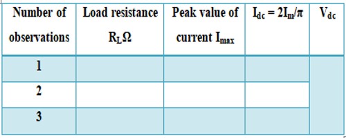
Idc = 2Im/π; Im = Peak value of current.
Table
Observation:
Output voltage Vdc has been observed by the oscilloscope and Vdc has been measured by a voltmeter.
Precautions:
- Positive terminals of capacitor, milliammeter, and voltmeter are to be connected jointly.
- Diodes D1 and D2 are to be taken of the same value.
- Step down transformer is to be used.
- The capacitor is to be used for getting smooth d. c. output.
- Ends of the wires are to be connected tightly.