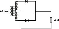
Bridge Rectification
The process by which alternating current (a.c.) is converted into direct current (d.c.) is called rectification and the circuit which is used in this work is called a rectifier. Rectifiers are mainly classified into three types: Half-wave rectifier, Center tapped full-wave rectifier and Bridge Rectifier. All these three rectifiers have a common aim that is to convert Alternating Current (AC) into Direct Current (DC).
Alternating current can be made one directional full wave by two ways; viz – (a) by a transformer and two diodes and (b) a transformer and four junction diodes. The last one is called a bridge rectification. For DC supply bridge rectifier is extensively used and is an effective circuit.
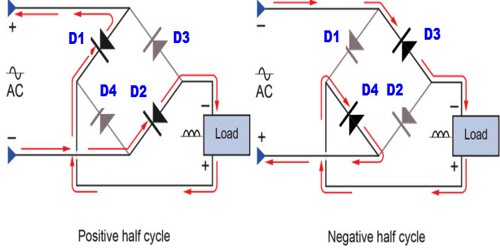
In order to decrease the input voltage a transformer is used and across that output of the transformer four diodes D1, D2, D3, and D4 are connected to form a bridge. In the figure, a. c. input has been connected through terminals MN and a resistor R is connected across the junctions P and B. It is called load. From the two ends of this resistor, the output is obtained.
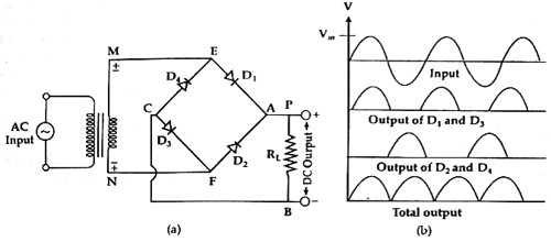
For the positive half cycle of the input terminal M of the secondary coil becomes + ye and N terminal becomes -ve. In this condition, the diodes D1 and D3 become forward biased. On the other hand diodes, D2 and D4 become reverse biased. In this situation, the current flow through MEABCFN path [Fig. (a)] and voltage are obtained across the two terminals of RL.
Again during the negative half cycle N terminal of the secondary coil will be positive and ‘M’ terminal will be negative. In this condition, diodes D2 and D4 will be forward biased. Then current will flow through the circuit NFABCEM path [Fig. (b)]. So, alternating current for each half cycle current flows through RL in one direction AB and in each case voltage drops across RL. Alternately, it can be said ‘A’ end of the bridge rectifier always acts as an anode and ‘B’ end acts as a cathode. In figure (b) input and output signals have been shown. In this way, for each AC signal, a DC is obtained in the output.