To meet the growing demand for accurate acceleration measurement in smaller navigation systems and other devices, researchers created a millimeter-thick accelerometer that generates a signal using laser light rather than mechanical strain. You’re driving down a two-lane road at the speed limit when a car barrels out of a driveway on your right. You slam on the brakes, and an airbag inflates within a fraction of a second of impact, saving you from serious injury or even death.
The airbag is activated by an accelerometer, which is a sensor that detects sudden changes in velocity. Accelerometers, among other things, keep rockets and airplanes on the correct flight path, provide navigation for self-driving cars, and rotate images on cellphones and tablets so that they stay right-side up.
Addressing the increasing demand to accurately measure acceleration in smaller navigation systems and other devices, researchers at the National Institute of Standards and Technology (NIST) have developed an accelerometer a mere millimeter thick that uses laser light instead of mechanical strain to produce a signal.
Although a few other accelerometers rely on light, the NIST instrument’s design simplifies the measuring process and provides higher accuracy. It also operates over a wider frequency range and has been rigorously tested than comparable devices.
The NIST device, known as an optomechanical accelerometer, is not only much more precise than the best commercial accelerometers, but it also does not require the time-consuming process of periodic calibrations. In fact, because the instrument measures acceleration with laser light of a known frequency, it could eventually serve as a portable reference standard to calibrate other accelerometers on the market, making them more accurate.
The accelerometer has the potential to improve inertial navigation in critical systems such as military aircraft, satellites, and submarines, particularly when no GPS signal is available. In the journal Optica, NIST researchers Jason Gorman, Thomas LeBrun, David Long, and their colleagues describe their work.
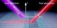
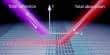
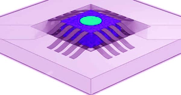
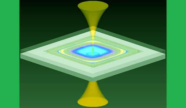
The principles of operation of a new accelerometer are demonstrated in this animation. Two silicon chips make up this optomechanical accelerometer. The first chip has a proof mass suspended by a series of silicon beams, allowing it to move vertically. The mass’s top has a mirrored coating. The second chip has a hemispherical mirror embedded in it. The optical cavity is formed by the mass and hemisphere mirrors working together. The device is illuminated with infrared laser light. The majority of frequencies are completely reflected.
Light with the resonant frequency, on the other hand, accumulates inside the cavity, increasing in intensity until the intensity of the light transmitted by the cavity matches the input. On the other side, light transmitted by the cavity can be detected. The length of the cavity changes as the device accelerates, causing the resonant frequency to shift. Researchers can determine the device’s acceleration by continuously matching the laser to the cavity’s resonant frequency. Sean Kelley/NIST Animation The research is part of NIST on a Chip, a program that brings cutting-edge measurement-science technology and expertise from the institute directly to users in commerce, medicine, defense, and academia.
Accelerometers, such as the new NIST device, measure velocity changes by tracking the position of a freely moving mass, known as the “proof mass,” relative to a fixed reference point inside the device. The distance between the proof mass and the reference point changes only when the accelerometer slows, accelerates, or reverses direction. The same is true if you are a car passenger. The distance between you and the dashboard remains constant whether the car is at rest or moving at a constant speed. However, if the car abruptly brakes, you are thrown forward, and the distance between you and the dashboard narrows.
The movement of the proof mass generates a discernible signal. The NIST researchers’ accelerometer uses infrared light to measure the change in distance between two highly reflective surfaces that bookend a small region of empty space. One of the mirrored surfaces is supported by the proof mass, which is suspended by flexible beams one-fifth the width of a human hair and can move freely. The other reflecting surface is an immovable microfabricated concave mirror that serves as the accelerometer’s fixed reference point.
The two reflecting surfaces, as well as the empty space between them, form a cavity in which infrared light of the appropriate wavelength can resonate, or bounce back and forth, between the mirrors, increasing in intensity. The wavelength is determined by the distance between the two mirrors, similar to how the pitch of a plucked guitar is determined by the distance between the fret and bridge. The resonant wavelength changes if the proof mass moves in response to acceleration, changing the separation between the mirrors.
A stable single-frequency laser is locked to the cavity to track changes in the resonant wavelength with high sensitivity. The researchers also used an optical frequency comb – a device that can be used as a ruler to measure the wavelength of light – to measure the cavity length with high accuracy, as described in a recent publication in Optics Letters. The ruler markings (comb teeth) can be compared to a series of lasers with equally spaced wavelengths. When the proof mass moves during a period of acceleration, either shortening or lengthening the cavity, the intensity of the reflected light changes as the wavelengths associated with the comb’s teeth move in and out of resonance with the cavity.
Converting the displacement of the proof mass into acceleration is a critical step that has proven difficult in most existing optomechanical accelerometers. The team’s new design, on the other hand, ensures that the dynamic relationship between the displacement of the proof mass and the acceleration is simple and straightforward to model using first principles of physics. In short, the proof mass and supporting beams are designed to behave like a simple spring, or harmonic oscillator, vibrating at a single frequency within the accelerometer’s operating range.
Because of this simple dynamic response, the scientists were able to achieve low measurement uncertainty across a wide range of acceleration frequencies — from 1 kilohertz to 20 kilohertz — without ever having to calibrate the device. This feature is unique because all commercial accelerometers must be calibrated, which takes time and money. Since the publication of their study in Optica, the researchers have made several improvements that should reduce the uncertainty of their device to less than 1%.
The optomechanical accelerometer detects accelerations as small as 32 billionths of a g, where g is the acceleration due to Earth’s gravity. It is capable of sensing displacements of the proof mass that are less than one hundred-thousandth the diameter of a hydrogen atom. That is a higher sensitivity than any accelerometer currently on the market with a comparable size and bandwidth.
With further advancements, the NIST optomechanical accelerometer could be used as a portable, high-accuracy reference device for calibrating other accelerometers without requiring them to be brought into a laboratory.