Experiment: Compare the electromotive forces of two electric cells by a Potentiometer
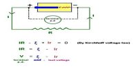
Theory: When the circuit remains open, then the potential difference between the two ends of a cell is equal to its electromotive force. Electromotive force is designated by E.
A potentiometer is a device used to compare the e.m.f. (electromotive force) of two cells, to measure the internal resistance of a cell, and the potential difference across a resistor. Suppose the electromotive forces of two cells are respectively E1 and E2. Let the current flowing through the primary circuit is ‘I’. For the electric cells having electromotive forces of E1 and E2 if the lengths from the positive terminal of the potentiometer from the null points are l1 and l2 respectively and resistance per unit length of the potentiometer is ‘ρ’ then from Ohm’s law we get,
E1 = potential drop = l1ρI … … … (1)
and, E2 = potential drop = l2ρI … … … (2)
By dividing equation (1) by equation (2) we get,
E1/E2 = l1ρI / l2ρI
or, E1/E2 = l1 / l2 … … … (3)
By inserting the values l1 and l2 to the above equations the ratio of E1 and E2 is determined.
Description of the instrument: The instrument by which the potential difference and electromotive force can be measured accurately by the method of fall of potential is called potentiometer. Electric current and resistance can also be measured with the help of this instrument.
In this instrument, ten pieces of manganin or constantan wire of uniform cross-section run parallel to each other are joined in series by thick copper strips at their ends. The wires lie on a plate mounted on a wooden platform [Figure]. Each wire in this instrument is 1 m long and the temperature coefficient of the resistance of the wire it very little.
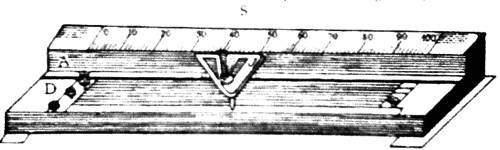
The first and the last ends of the wire are connected to two terminal screws A and D. There is a meter scale at one end of the wooden frame parallel to the wire. With this scale distance of any point on the wire can be measured from one end of the wire. A triangular jockey J made of brass is there on the platform which can move right and left along the length of each wire. It contains a central tapping key at the center. By shifting the jockey back and forth and by pressing the key contact can be made with any point of the wire of the potentiometer.
Necessary instruments:
(1) Potentiometer, (2) two experimented cells, (3) a storage cell, (4) galvanometer, (5) one one-way key, (6) one two-way key, (7) resistance box, (8) Rheostat or variable resistance (Rh), (9) connecting wires, (10) sandpaper etc.
Procedure:
(1) First of all the terminals of connecting wires, connecting points of the galvanometer, potentiometer, rheostat, resistance box, keys etc. are to be rubbed thoroughly by sandpaper. Different connections at the two terminals A and B of the potentiometer are given.
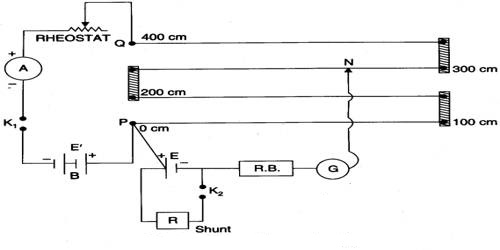
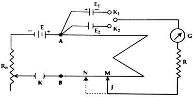
(2) The circuit is connected according to the figure-2. Positive terminals of the experimental cells E1 and E2 and that of the storage cell are connected to the terminal A of the potentiometer. With the common terminal of the two-way key, the galvanometers G. High resistance box R and jockey J are connected. The negative end of the storage cell E, rheostat Rh, and the key K are connected with end B of the potentiometer.
(3) After completing the circuit connectors following the procedure mentioned in 2 above, 2000 Q resistance from the resistance box R is inserted in the circuit and by taking high value in Rh, and closing the key K, the jocky J is touched once to one end and then to the other end of the potentiometer. If due to touching in the opposite ends the galvanometer gives deflection in opposite direction, then it is considered that the circuit connection is alright.
(4) Now by closing the keys K and K2 successively the cells E1 and E2 are included in the galvanometer circuit. Following the procedure (3) it is checked whether the deflections of the galvanometer are on both sides or not. It is to be remembered that the potential difference of the storage cell must be greater than the experimental cells E1 and E2. Otherwise, the galvanometer will not show deflection on both sides.
(5) Now closing the two-way key K1 the cell E1 is included in the galvanometer circuit and by touching the jockey at different points of the potentiometer wires the point in the wire is found out where the galvanometer shows zero deflection. It is called null point. Now the value of Rh, is made the minimum and the final null point is found out. Let us consider that the distance of this null point M from the end ‘A’ is l1 cm.
(6) Now the two-way key K1 is made open and the second cell E2 is included in the galvanometer circuit and following the procedure (5) null point is determined. Say, the distance of this null point N is I2 cm.
(7) From the resistance box different resistances are taken out and following the procedures (5) and (6) at least three times the value of lengths l1 and 12 are found out. In each observation ratio of E1 and E2 is determined and finally, an average of them is found out.