Conducting wire and force in magnetic field
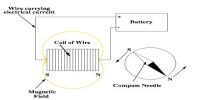
We know when current flow through a conductor magnetic field is produced. On a rectangular frame of aluminum, a thin insulated copper wire is wrapped many times to form a coil and is placed between the poles of a permanent horseshoe magnet NS and current are allowed to flow through the wire. This technique is used in moving coil galvanometers. Magnetic force and torque produced due to the flow of current in the coil placed in the magnetic field are discussed below:
Torque on a current carrying coil in magnetic field
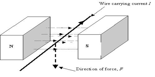
We know that if a wire carrying current is placed in a magnetic field or a magnetic field is applied on a wire carrying current a magnetic force acts on it. The magnitude of this force is,
F = IlB sinθ …. …. …. (1)
and its vector form,
F→ = Il→ x B→
Here l→ is the displacement vector whose direction is along the direction of current in case of a straight wire.
If a loop of wire carving current is hung properly in a uniform magnetic field, then the magnetic force creates torque or torsional force on the loop which tends to rotate or turn the loop. This torque or torsional force is used to operate many different devices or instruments, e.g., galvanometer, electric motor, generator etc. Now we will derive the equation of torque for a rectangular loop of wire.
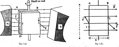
Let ABCD be a very small rectangular loop or coil carrying current placed in a uniform magnetic field B. The plane of the coil is in a parallel position to the magnetic field. The loop is attached to a shift or rod in such a way as it can rotate freely [Fig. a]. The resultant of the force acting on four arms AB, BC, CD, and DA will act as the net force in the loop. As the loop is rectangular, so
AB = DC = b (Width of the loop)
and AD = BC = l (Length of the loop)
Let the current I flow clockwise. Now the force applied on the arm AB (according to equation (1)] is,
F = lb B sinθ
= 0 [angle between b→ and B→, θ = 0]
Again, the force acting on CD.
F = lbB sinθ = 0 [as we know, θ = 1800]
Since the forces acting on AB and CD are equal and opposite, so there will not be any displacement and as the line of action of the forces is in the same line, so no couple will be created. The force acting on the arm AD.
F = IlB sin θ = IlB (angle between l and B, θ = 900)
and the force on BC.
F = IlB sin θ = IlB (θ = 900)
According to the right-hand rule, the forces acting on AD and BC will be opposite to each other and their line of action not being in the same straight line, the loop will experience a torque or torsional force; consequently, the loop will turn or rotate with respect to the rod. Now,
Net torque = Force x perpendicular distance between the forces acting.
= F x b = IlB x b = Ilb B = IAB
Here A = lb, the area of the loop.
If a coil is made by wrapping N number of turns of a wire, then the force acting on each side of the coil will be N times that of a single loop and hence torque will also be N times. In that condition, net torque, τ = NIAB
If the plane of the coil makes an angle θ with the magnetic field i.e., the angle between b→ and B→ is θ [Fig. 2], then the distance between the forces,
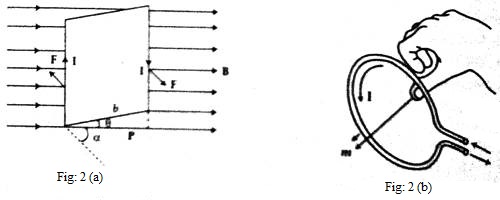
p = b Cos θ
so, τ = NIaB cos θ
= NIaB cos (900 – α), where α is the angle between the normal to the loop and B,
= NIaB sin α.
In vector form, it can be written as,
τ = NIa→ x B→ … …. …. (2)
NIa→ is called magnetic moment M of the coil. The direction of M will be along the direction of A→.
So, τ = M→ x B→.
That means the product of the current of a current carrying coil and the area of the coil is called the magnetic moment of that coil.
Determination of the direction at m→:
If the fingers of the right hand represent the direction of the current, then the direction shown by the thumb will be the direction of m→ [Fig. 2 (b)].
More the magnetic moment of the coil carrying current more torque will be experienced by the coil when placed in the magnetic field. From equation (2), it is seen that by increasing the number of turns of the coil and the area of cross-section, the magnetic moment of the coil can be increased.
