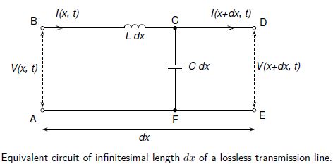
We will only discuss lossless transmission lines, i.e. where there is no resistance present between or along the conductors. Then the equivalent circuit of infinitesimal length dx is shown in below Fig. Note that here and in the following equations L is the inductance per unit length and C is the capacitance per unit length.

Applying Kirchhoff’s loop rule to loop ABDEA,
V (x, t) — Ldx [ ϐI (x,t)/ϐt] – V(x + dx, t) = 0,
and Kirchhoff’s junction rule to junction C gives
I (x, t) – C dx [ ϐB (x,t)/ϐt] – I (x + dx, t) = 0
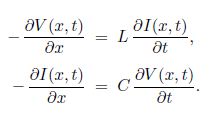
Thom these we obtain the lossless transmission line equations also known as the telegraphers’ equations

If instead we differentiate Equation with respect to t and with respect to x, and then eliminate ϐ2V/ϐxϐt, that, we get

which is the wave equation for I (x,t) on a lossless transmission line.
For harmonic time-dependence with angular frequency ω we can use complex exponentials

where k = ω/vp, and Vf and Vb are the complex voltage amplitudes of waves propagating in the forward and backwards directions, i.e. in the positive and negative x-directions (we take the real parts for the actual voltage and current). Similarly, If and Ib are the complex current amplitudes of waves propagating in the positive and negative x-directions.
The characteristic impedance of the transmission line is
Z = Vf/ If = Vb/ Ib
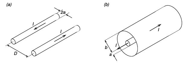
As an example, we consider two types of transmission line, the two-wire transmission line (Fig a) and the coaxial cable (Fig b).

For two ware transmission line:
L = μ/π Ln (D/a); C = πƐ/ Ln (D/a)
And so,
Vp = 1/√(μƐ; Z = 1/π √(μ/Ɛ ln (D/a)
Notice that in both cases vp is the same and equal to (μƐ)-1/2 for the insulating material having permeabilityµ and permittivity Ɛ — this is true for any lossless transmission line — but that Z depends on the geometry (type and dimensions) of the transmission line.


