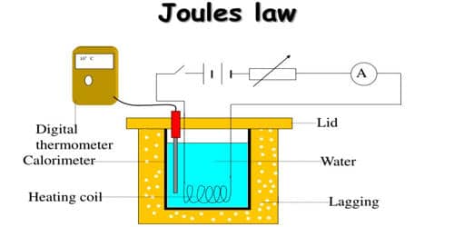
Joule’s law is verified using Joule’s calorimeter. Joule effect and Joule’s law are any of several different physical effects discovered or characterized by English physicist James Prescott Joule. It consists of a resistance coil R enclosed inside a copper calorimeter (Figure).
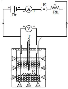
Fig: Joule’s calorimeter
In this experiment, we investigate how the temperature of the water and calorimeter change with the current flowing through the heating element. The ends of the coil are connected to two terminals, fixed to the lid of the calorimeter. A stirrer and a thermometer T are inserted through two holes in the lid. Two-thirds of the volume of the calorimeter is filled with water. The calorimeter is enclosed in a wooden box to minimize the loss of heat.
A battery (Bt), a key (K), a rheostat (Rh) and an ammeter (A) are connected in series with the calorimeter. A voltmeter (V) is connected across the ends of the coil R.
[Note: In the lab. this is a very time-consuming experiment as each different current must be allowed to flow for at least 5 minutes. In this simulation, 90 seconds is sufficient for each current.]
Procedure: (in the laboratory)
- Use the slider to set the current value to 0.5 A.
- Note the starting temperature and current and record in a table.
- Press “Close Circuit”. The current begins to flow in the heating coil and the timer starts. Note: A very small rise in temperature occurs when the current is at 0.5 and 1A.
- After 90 seconds, press “Open Circuit”. Record the rise in temperature.
- Press “Reset” and again use the slider to set the current to 1 A. Record the starting temperature and current.
- Repeat steps 3 to 5 until at least six readings have been taken.
Verification of Joule’s Law
Law of resistance:
The same amount of current ‘I’ is passed for the same time t through different coils of resistances R1, R2, R3, etc. The corresponding quantities of heat gained H1, H2, H3, etc. are calculated. It is found that,
H1/ R1 = H2/ R2 = H3/ R3
H/R = Constant
i.e H α R. Hence, the law of resistance is verified.
Law of time:
The same amount of current I is passed through the same resistance R for different intervals of time t1, t2, t3, etc. The corresponding quantities of heat gained H1, H2, H3, etc. are calculated.
It is found that
H1/ t1 = H2/ t2 = H3/ t3
H/t = constant
i.e H α t. Hence, the law of time is verified.
Law of current
The initial temperature of the water is measured as θ1. Let W be the heat capacity of the calorimeter and contents. Now a current of I1 is passed for a time of t (about 20 minutes). The final temperature (θ2) is noted. The quantity of heat gained by the calorimeter and the contents is calculated as H1 = W (θ2 – θ1). Water is then cooled to θ1. The experiment is repeated by passing currents I2, I3 … etc., through the same coil for the same interval of time t and the corresponding quantities of heat H2, H3, etc. are calculated. It is found that –
H1/I1 = H2/I2 = H3/I3
i.e., H/I2 = a constant
i.e., H ∞ I2
i.e. Hence, the law of current is verified.
Precautions:
- Ensure that the current remains constant at each value. Adjust the variable resistor if necessary.
- Ensure that the heating coil is completely covered with water to avoid heat loss as measured by the thermometer.
- Use a well-insulated container.