According to Pascal’s law, “The outer static pressure applied on a confined liquid is distributed or transmitted consistently throughout the liquid in all directions.” The static pressure acts at right angles to any surface in contact with the fluid.
Applications of Pascal’s law:
(i) Hydraulic lift
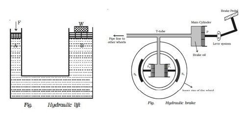
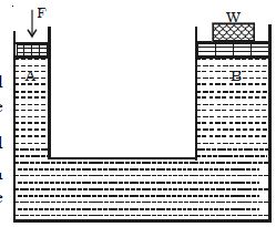
An important application of Pascal’s law is the hydraulic lift used to lift heavy objects. A hydraulic lift is versatile in its utility. A schematic diagram of a hydraulic lift is shown in the Figure. It consists of a liquid container that has pistons fitted into the small and large opening cylinders. It has a hydraulic apparatus which is used to lift heavy objects. If a1 and a2 are the areas of the pistons A and B respectively, F is the force applied on A and W is the load on B, then
F/a1 = W/a2 or, W = F (a2/a1)
This is the load that can be lifted by applying a force F on A. In the above equation (a1/a2) is called the mechanical advantage of the hydraulic lift. One can see such a lift in many automobile service stations. It works based on the principle of equal pressure transmission throughout a fluid (Pascal’s Law). In the case of hydraulic lifts, force applied creates “lift” and “work.” The hydraulic lift technology has widespread applications in the industrial, construction, transport sector, etc.
Few more applications include a hydraulic jack and hydraulic press and forced amplification is used in the braking system of most cars. These are described below.
(ii) Hydraulic brake
When brakes are applied suddenly in a moving vehicle, there is every chance of the vehicle to skid because the wheels are not retarded uniformly. In order to avoid this danger of skidding when the brakes are applied, the brake mechanism must be such that each wheel is equally and simultaneously retarded. A hydraulic brake serves this purpose. It works on the principle of Pascal’s law. Hydraulic brakes are used in cars, motorcycles, and lorries.
The figure shows the schematic diagram of a hydraulic brake system. The brake system has a main cylinder filled with brake oil. The main cylinder is provided with a piston P which is connected to the brake pedal through a lever assembly.
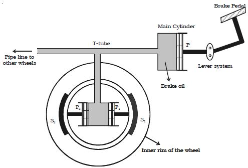
Fig: Hydraulic brake
A ‘T’ shaped tube is provided at the other end of the main cylinder. The wheel cylinder having two pistons P1 and P2 are connected to the T tube. The pistons P1 and P2 are connected to the brake shoes S1 and S2 respectively.
When the brake pedal is pressed, piston P is pushed due to the lever assembly operation. The pressure in the main cylinder is transmitted to P1 and P2. The pistons P1 and P2 push the brake shoes away, which in turn press against the inner rim of the wheel. Thus the motion of the wheel is arrested. The area of the pistons P1 and P2 are greater than that of P. Therefore a small force applied to the brake pedal produces a large thrust on the wheel rim.
The main cylinder is connected to all the wheels of the automobile through pipe line for applying equal pressure to all the wheels. The frictional force between these force components causes the vehicle to stop.
(iii) Hydraulic Jack
Hydraulic jacks, which come under the category of a closed container, follow the principle of Pascal’s Law. They are used to lift heavy bodies. Hydraulic jacks are highly advantageous in the automotive industry and are often used to lift cars above the ground level for repair and maintenance.
(iv) Hydraulic Pumps
Hydraulic pumps, which convert mechanical energy into hydraulic energy, facilitate the movement of a fluid, and here, yet again, Pascal’s Law comes into play. It helps in the discharge of fluid. Hydraulic pumps are used widely in the automobile industry.