V-I characteristic curve of Junction Diode
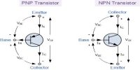
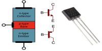
If a p-type and n-type semiconductors are connected by a special technique then the junction surface is called a p-n junction. It is one of the simplest semiconductor devices around, and which has the characteristic of passing current in only one direction only. One part of a pure semiconductor crystal is made p-type and the other part n-type by doping impurities in a controlled way at high temperature and the p-n junction is made.
For the use of a p-n junction as a part of a circuit, its forward bias and reverse bias characteristics are to be known. That means the variation of current is to be known for forward and reverse voltages.
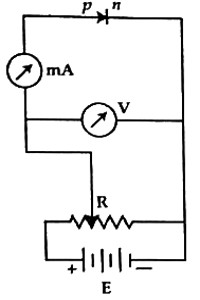
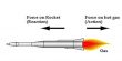
In the figure, a p-n junction is shown for forwarding bias. In the circuit ammeter, A for diode current and voltmeter V for diode voltage measurement have been used. An ammeter is connected always in series and the voltmeter is always connected in parallel in the circuit. In order to change the applied voltage in the diode, a variable resistor is used. Now voltage is increased gradually from
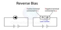
zero and the corresponding current increases along with the voltage. Now the battery connection is reversed and a reverse bias is applied in the diode. Like the forward bias here also current will change slightly with increasing voltage. If a graph voltage current is drawn, then the graph will be like fig. 2.
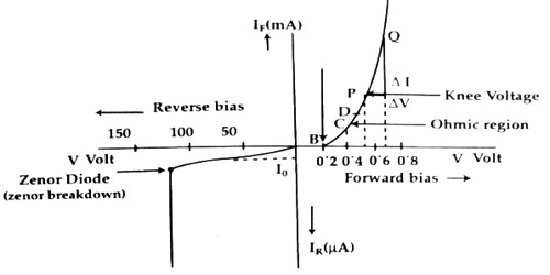
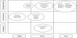
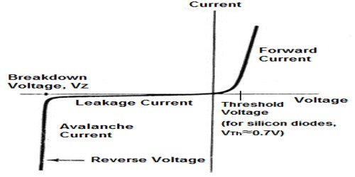
From the V — I curve, the following characteristics are observed –
In case of forward bias:
(i) Current does not increase as soon as voltage increases. Up to 0.3V for germanium and 0.7V for silicon, the forward current remains zero. 0.3V and 0.7V is respectively an internal potential barrier for germanium and silicon respectively. That means, in order to overcome the potential barrier minimum voltage V0 is needed for charge flow. It is called an operating voltage.
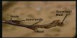
(ii) When VF > V0, then to a certain increase of voltage (V) current IF continues to increase after crossing the potential barrier. Change of V and I obey Ohm’s law. For this reason, this region is called the Ohmic region. BC is the Ohmic region in the graph.
(iii) After crossing the Ohmic region, for a small change of voltage, a large change of current occurs and the graph looks like the bending of a knee. The voltage for which current increases rapidly is called knee voltage. In the graph D is the knee voltage.
In case of reverse bias:
(i) With the increase of reverse voltage current also increases and reaches to lo. Afterward, current remains constant even though the voltage is changed. Current 10 is called reverse saturation current or leakage current. This current is produced by the small number of ‘minority charge carriers’ in the p and n region. Its value is normally a few μA. Since a number of minority carriers do not change due to the change of voltage, hence current remains steady even though the voltage is changed. Only due to change in temperature number of minority carriers changes.
(ii) By increasing the reverse bias to a critical value, it is seen that current suddenly increases manifold. This time the resistance of the p-n junction breaks down completely.